OSPF Loop Prevention
Recently I realized I had some questions on just how OSPF prevented loops. So as any curious mind would I did some research and decided to lab it up in GNS3. It was kind of difficult researching this topic online as there were very few examples online. Luckily I found a few and through some reading I was about to learn and expand my brain a bit. Before we can deep dive into how OSPF can prevent routing loops, we have to take a look at some OSPF basics. Specifically Area 0, OSPF LSA types and OSPF router roles such as the Area Border Router.
OSPF Basics
-
OSPF is a link-state routing protocol that uses messages called Link State Advertisements (LSA) to share routing information. There are 11 different LSA packets but we will only be discussing the first three and how they work.
- LSA Type 1 - Router
- Sent between routers in a single area and does not leave the area of origin. Used to describe the cost of the link as well any neighboring routers on the link.
- LSA Type 2 - Network
- Originated by the Designated Router (DR) and like Type 1 LSAs are only flooded within a single area. Type 2 LSAs advertise information about all the connected routers (including the DR itself) in the network segment.
- LSA Type 3 - Summary
- Sent by the ABR to advertise the routes in another area. The ABR will send Type 3 LSAs to another area to describe the topology. The routers in the neighbor area will know to reach those routes via the ABR. The ABR also uses Type 3 LSAs to advertise destinations within its area to the backbone.
OSPF Backbone Area & Area Border Routers
-
The backbone area (Area 0) is required when multiple areas are included within an OSPF topology. In order for one area to reach another area the traffic must pass through the backbone area. ABRs will send Type 3 LSAs through the backbone area which will be forwarded to the next area. This is important and one way OSPF prevents routing loops.
-
Area Border Routers act as the middle man between the backbone and other areas. To be considered an ABR an interface must exist in both Area 0 and another area. ABR’s expect Type 3 LSAs only from Area 0. Any Type 3 LSA recieved from a non-backbone area will be ignored. However an ABR will accept Type 3 LSA’s if a router has a partial adjacency to Area 0 (which we will be testing). This doesn’t necessarily mean those routes will be used so keep that in mind.
Time To Lab
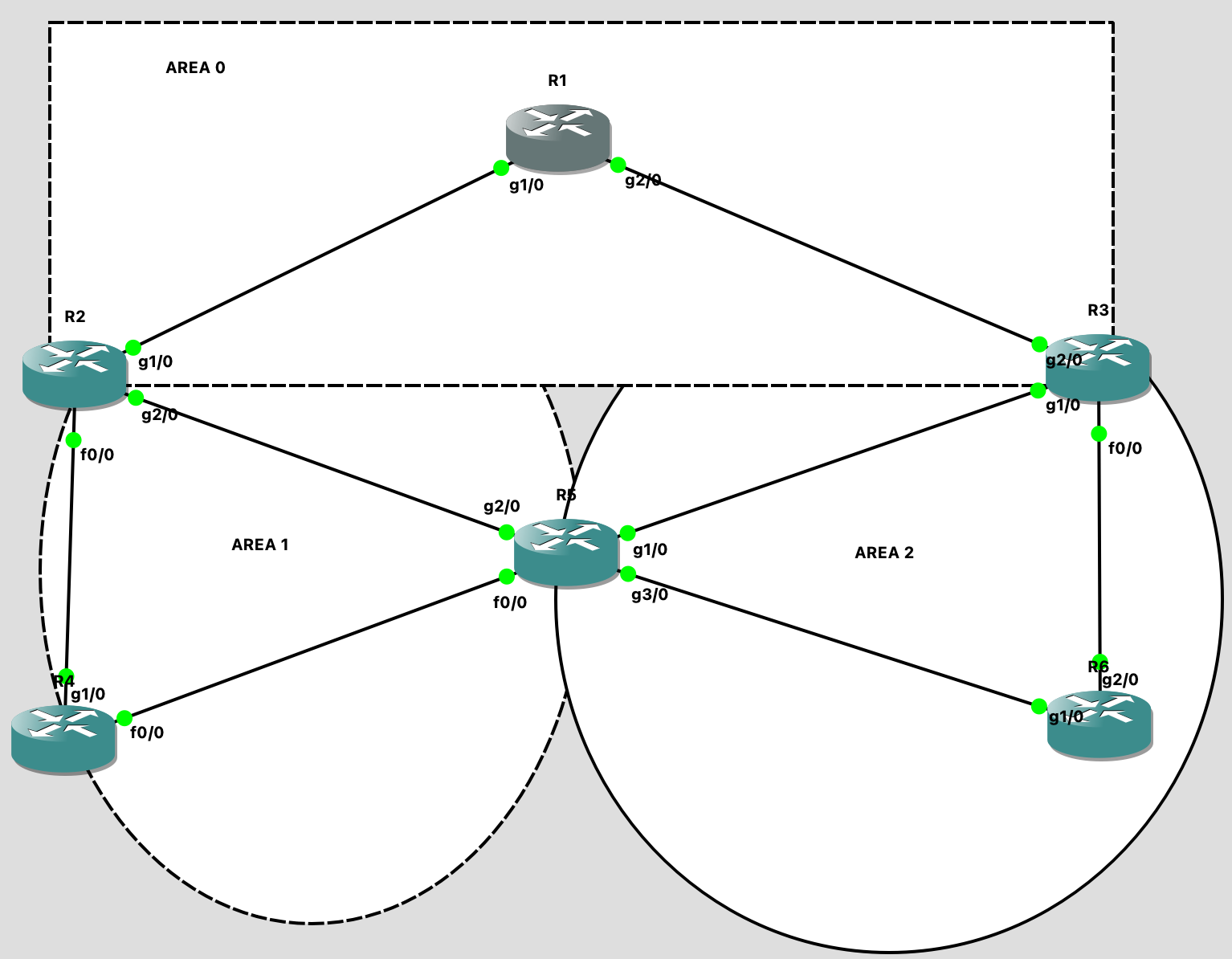
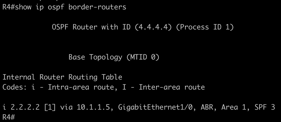
- Here is the topology we will be working with in GNS3. As you can see we have 3 areas - Area 0, 1 and 2. How many ABR’s do you see here? 2 or 3? R2 and R3 are ABR’s but R5 is not. Remember to be considered an ABR you must have an interface located in the backbone area and an interface in another area. Taking a look at the “show ospf border-routers” command on R4 it seems to only recognize R2 as an ABR in Area 1, not R5.
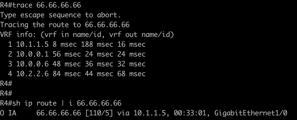
- There is a route on R6 shared via OSPF for the address 66.66.66.66/32 sitting on router R6. The current path to this address is via R2, which makes sense because of the OSPF rule that traffic must pass through the backbone for inter-area traffic.
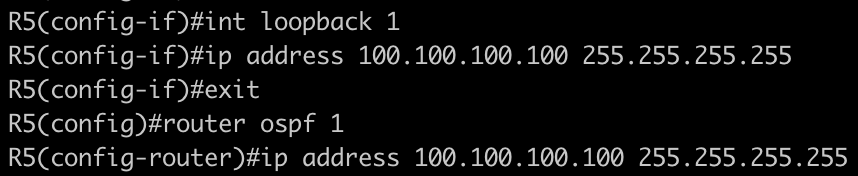
- What if we wanted to use the path through R5 instead? How can we make that happen? We can place an interface on R5 into Area 0! This will provide R5 with a partial adjacency to Area 0 and R4 will then see R5 as an ABR. The route for 66.66.66.66 should route through R5 at that point. We will place a loopback address on R5 into Area 0 to make this happen.
- There now that R5 has a connection to Area 0 let’s take a look at R4 and see if it will route through R5.
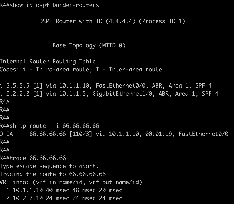
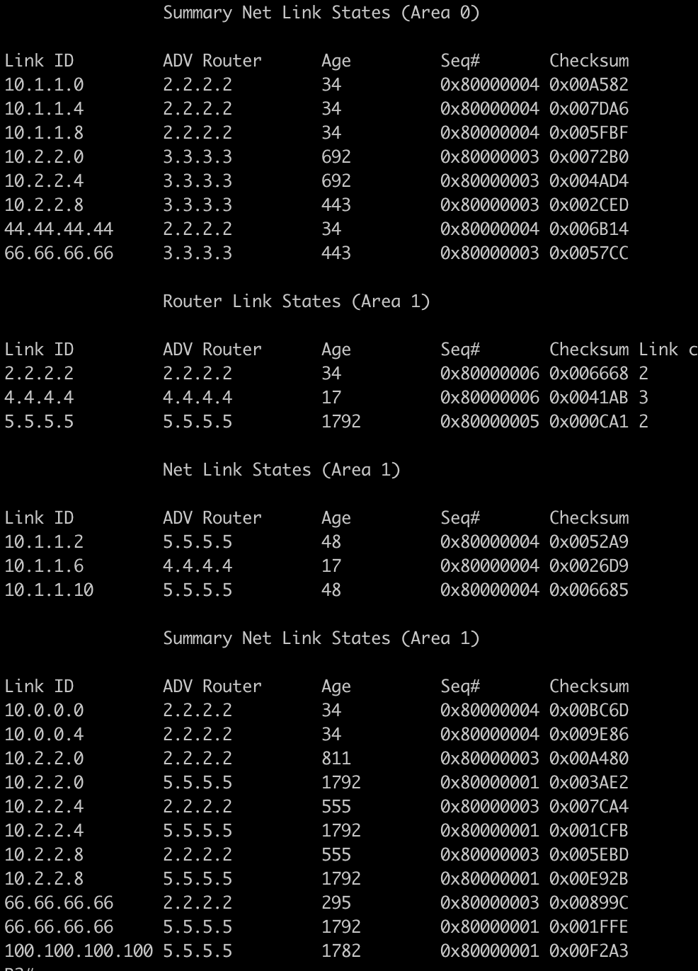
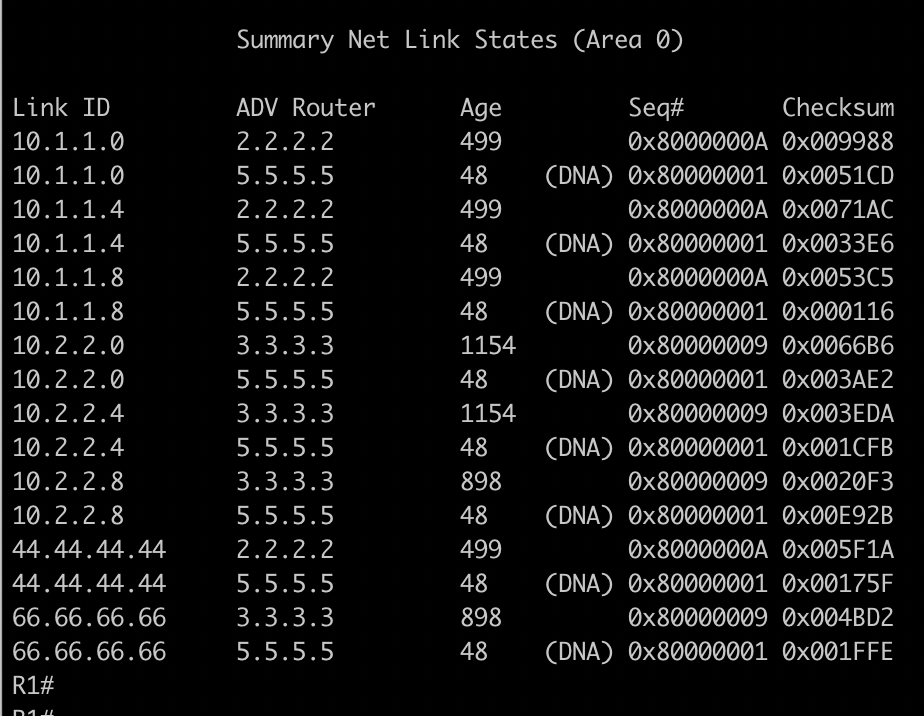
- Nice! So it looks like a few things have occured on R4. It now views R5 as an ABR and was able to receive Type 3 LSA’s from it. This caused the route to be added into the route table with a cost of 3 instead of 5! Finally the traceroute was performed and you can see it is now using the optimal path towards 66.66.66.66/32. But what about R2? R2 has a full adjacency with Area 0 and should have also received the Type 3 Summary LSA from R5. Will it now use the new path? if we take a look we can see it does not! ABR’s only expect Type 3 LSA’s from the backbone Area 0 and because R5 only has a partial adjacency to Area 0 it will not install that route into it’s table and ignore it. Even though if we look at the OSPF database it has received the summary LSA from Area 1 it will only use the LSA from Area 0.

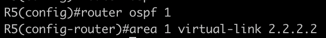
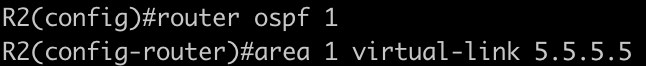
- To make R5 have a full adjacency to Area 0 you can create a virtual link to resolve the problem. A virtual link between R5 and R2 will allow R5 to connect with Area 0 and be viewed as a ABR. Here we will configure the virtual link between R5 & R2 using Area 1 as the transit area to the backbone.
- With the virtual link now configured between R5 & R2 lets check the if R2 can see R5 as an ABR.
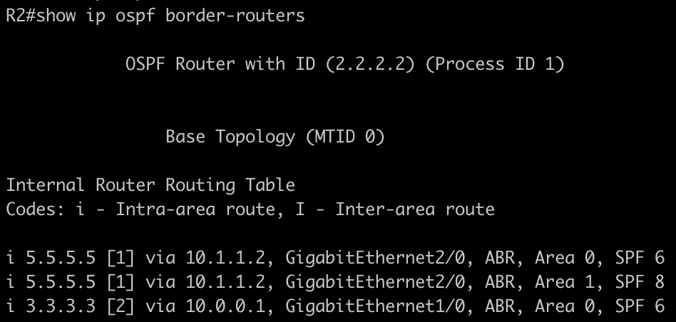

- Wow would you look at that? R2 now considers the R5 and is using tha path through R5 to reach 66.66.66.66 instead of going through the backbone. R1 is also accepting the Type 3 LSAs from R5 as they are now being passed on by R2.
What Did We Learn?
- So we took a dive into OSPF loop prevention. We learned the purpose of the ABR and how it interacts with Type 3 LSA’s coming from the non backbone areas. We also learned about virtual links and how to configure them. We saw that ABR routers will not pass on Type 3 LSA routes learned from non-backbone areas into the backbone. We gained a better understanding of how OSPF functions and the way the routers interact with each other based on the OSPF rules. Overall I felt this was a great lab and I encourage you to set up a topology like this to learn it yourself.